
- The Base Unit and Its Axes
- Why Working-Range Limits Matter
- Defining Limits from the Part Envelope
- Verifying with Laser-Off Jog Runs
- Documenting per Fixture Family
- Frequently Asked Questions
- What are the maximum axis travels for the Simass Base Unit?
- How do I prevent collisions when configuring axis travel?
- Can I save different axis configurations for multiple fixtures?
- Why should I document axis travel settings for each job?
- Related Articles
Quick Answer: To configure axis travel lengths for the Simass Base Unit, use the control software to set soft limits based on your part and fixture envelope. Jog the axes with the laser off to verify clearances, and document limits for each fixture family to ensure safe, repeatable operation across sectors.
| Axis | Maximum Travel (mm) |
|---|---|
| X | up to 1010 |
| Y | up to 1110 |
| Z | up to 510 |
Values reflect the maximum programmable travel for each axis as described for the Simass Base Unit. Actual usable travel may be limited by installed modules or fixture setup.
The Base Unit and Its Axes
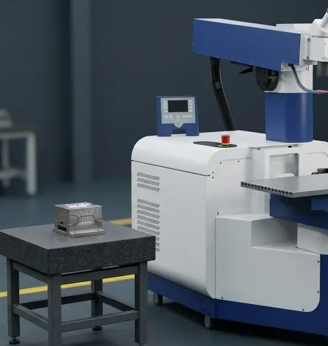
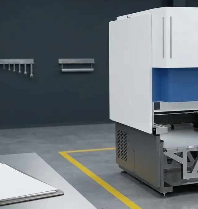
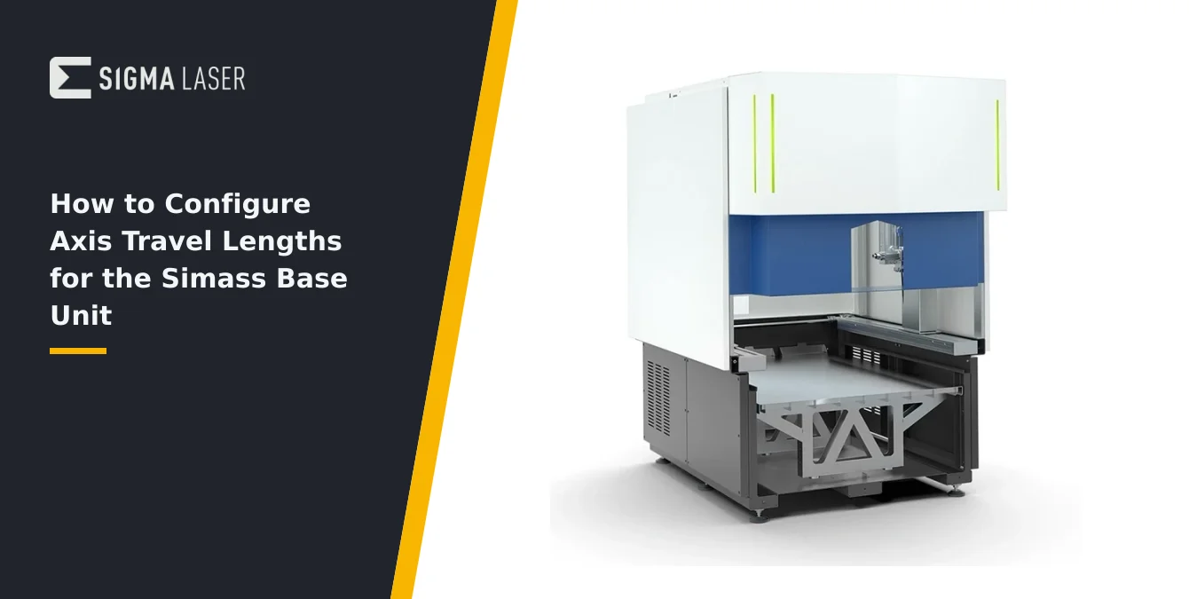
The Simass Base Unit is a modular automatic laser welding workstation designed for flexible, high-precision production environments. At its core, the base unit integrates the primary motion axes—X (up to 1010 mm), Y (up to 1110 mm), and Z (up to 510 mm)—which define the machine’s working envelope. These axes are engineered for robust, repeatable movement, supporting a wide range of part sizes and geometries. The base unit also contains essential supply elements, such as power distribution, cooling, and process control interfaces, ensuring reliable operation during extended production cycles.
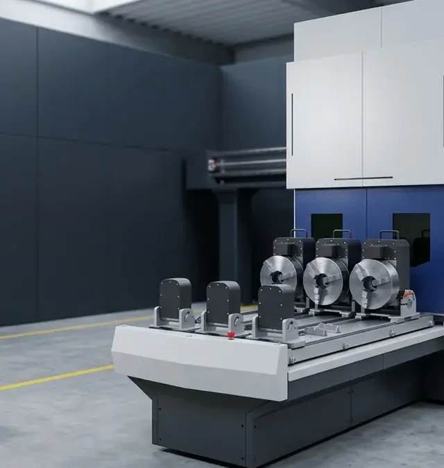
One of the defining features of the Simass Base Unit is its modularity. Operators can configure the system with interchangeable modules—Rotate, Slide, or Powder—tailoring the workstation to specific production needs. The Rotate module introduces a precision rotary table for indexed or continuous part rotation, ideal for circumferential welds. The Slide module enables parallel loading and unloading of larger or longer parts via multiple motorized slides, dramatically reducing downtime. The Powder module, available as a catalogue option, automates powder application for repair welding tasks. Each module can be retrofitted or swapped as requirements evolve, preserving the value of the core investment.
The axes themselves are designed for both flexibility and safety. Their travel limits (X≤1010 mm, Y≤1110 mm, Z≤510 mm) accommodate a broad spectrum of workpieces, from compact medical components to large tooling or automotive parts. The open, modular structure allows for easy integration of custom fixtures and handling devices, supporting a variety of production workflows. Understanding the physical and programmable limits of these axes is fundamental to safe, efficient operation—especially when reconfiguring the workstation for new modules or part families.
In summary, the Simass Base Unit’s axis configuration is foundational to its adaptability and productivity. Proper setup ensures that each module operates within safe, defined boundaries, supporting high-quality, repeatable welds across multiple industrial sectors.
Why Working-Range Limits Matter
Establishing precise working-range limits for each axis is critical to safe and efficient operation of the Simass Base Unit. These limits serve as programmable boundaries within which the axes can move, protecting both the equipment and the workpiece from accidental collisions. Without clearly defined limits, there is a significant risk of the tool head or fixture contacting the machine frame, module components, or other installed accessories—potentially causing costly downtime or damage.
From a production standpoint, well-defined axis travel limits directly impact cycle time and process repeatability. By constraining movement to the minimum area required for the current part and fixture, operators can reduce unnecessary axis travel, minimizing non-productive motion and optimizing throughput. This is especially important in automated or semi-automated workflows, where small inefficiencies can accumulate into substantial lost time over the course of a production shift.
Repeatability is another key consideration. Once working-range limits are set for a given part and fixture family, the system can reliably return to programmed positions, ensuring consistent weld quality across multiple cycles. This is particularly valuable in sectors such as medical device manufacturing or automotive component production, where process consistency is paramount. Axis travel configuration also supports changeover efficiency: by documenting and recalling limit settings for each fixture family, operators can rapidly retool the workstation for new jobs without risking setup errors.
Finally, working-range limits contribute to operator safety. By preventing the axes from exceeding safe boundaries, the risk of unexpected movement or entrapment is minimized. This is a core aspect of best practice in laser welding environments, where both optical and mechanical hazards must be managed. In summary, configuring axis travel lengths is not just a technical requirement—it is fundamental to protecting equipment, ensuring process quality, and maintaining a safe production environment.
| Practice | Purpose |
|---|---|
| Set soft limits in control software | Define safe, programmable boundaries for each axis |
| Verify with laser-off jog runs | Physically check clearances and prevent collisions |
| Document limits for each fixture family | Enable rapid, error-free changeover |
| Maintain margin to hard stops | Provide buffer for setup variation and thermal expansion |
Following these practices ensures safe, repeatable, and efficient operation of the Simass Base Unit across different setups and modules.
Defining Limits from the Part Envelope
Configuring axis travel lengths begins with a clear understanding of the part envelope—the three-dimensional space occupied by the workpiece and its fixture during welding. Operators should assess not only the dimensions of the part itself but also any additional space required for fixturing, clamping, and tool clearance. This ensures that the programmed axis limits accommodate all necessary movements without risk of collision or overtravel.
Soft limits are typically established via the control software, allowing operators to define the maximum permissible travel for each axis based on the current setup. This approach provides a programmable safety margin, preventing the axes from moving beyond defined boundaries even if an incorrect command is issued. When setting these limits, it is important to account for the full range of motion required for welding, including any approach or retract movements, as well as access for loading and unloading parts.
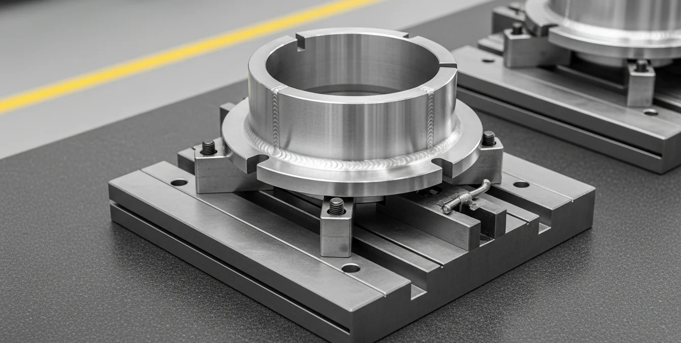
Fixture clearances are a critical consideration. Operators should verify that the soft limits leave sufficient space between the tool head and all fixture components throughout the entire welding cycle. This includes accounting for any protruding clamps, supports, or sensors that might extend into the axis travel path. In cases where multiple fixture variants are used, it is best practice to define and document separate soft-limit profiles for each family, ensuring that the system can be quickly reconfigured without manual recalculation.
It is important to note that the exact steps for setting soft limits will depend on the control software version and installed modules. Operators should refer to the supplied documentation and use the available software interface to enter limit values. Avoid guessing or extrapolating menu paths; instead, use the control panel or software tools provided with your system to define and verify axis boundaries. This methodical approach ensures that axis travel configuration is both accurate and repeatable across different setups.
Verifying with Laser-Off Jog Runs
After setting preliminary axis travel limits in the control software, operators should perform a series of laser-off jog runs to physically verify the usable travel range. This involves manually moving each axis to its programmed extremes, observing the actual clearances between the tool head, workpiece, fixture, and any installed modules. By conducting these checks with the laser source disabled, operators can safely identify potential collision points or areas where additional margin may be needed.
During the jog run, it is advisable to move each axis slowly and monitor for any unexpected resistance or obstructions. Operators should record the precise positions where the tool head approaches hard stops or comes within a safe distance of the fixture. Maintaining a margin to hard stops—typically several millimeters, depending on the application—provides a buffer against mechanical overtravel and compensates for minor setup variations or thermal expansion during operation.
It is also important to check the entire programmed motion path, not just the endpoints. This includes any intermediate positions, approach vectors, or compound movements that may occur during the welding cycle. Operators should pay special attention to areas where the tool head passes close to clamps, supports, or rotary/slide modules, as these are common sources of unexpected interference.
- Move each axis to its soft-limit positions and visually inspect clearances.
- Record the minimum and maximum positions for future reference.
- Adjust soft limits as needed to maintain a safe margin from hard stops and fixtures.
- Repeat the process for each new fixture or part family.
This hands-on verification process is essential for ensuring that the configured axis travel lengths are both safe and practical for the intended operation. It also provides valuable feedback for refining soft-limit settings and documenting best practices for future setups.
| Module | Function |
|---|---|
| Rotate | Precision rotary table for indexed or continuous part rotation (circumferential welds) |
| Slide | Parallel loading/unloading of larger or longer parts via multiple motorized slides |
| Powder | Automated powder application for repair welding tasks (catalogue option) |
Each module can be retrofitted or swapped as requirements evolve. Modules are designed to tailor the Simass Base Unit to specific production needs.
Documenting per Fixture Family
Once axis travel lengths have been configured and verified for a specific part and fixture combination, it is essential to document these settings for future reference. The Simass Base Unit supports program memory, allowing operators to store multiple setup profiles corresponding to different fixture families or production jobs. This capability streamlines changeovers and ensures that each setup can be quickly recalled with its associated axis limits, motion sequences, and process parameters.
In sectors such as tooling, medical device manufacturing, automotive, food and packaging, and aerospace, production requirements often involve frequent part changes and varying fixture designs. By maintaining a documented record of axis travel configurations for each fixture family, operators can minimize setup time and reduce the risk of configuration errors. This documentation should include the defined soft limits for each axis, notes on fixture clearances, and any special considerations related to the installed module (Rotate, Slide, or Powder).
Best practice is to integrate this documentation into the program memory or job management features of the control software. Operators can label each stored setup with a clear identifier—such as part number, fixture type, or production batch—making it easy to retrieve the correct configuration when needed. This approach not only supports efficient workflow but also enhances traceability and process control, which are critical in regulated industries.
Finally, regular review and updating of fixture family documentation is recommended. As new parts or fixtures are introduced, or as process requirements evolve, operators should revisit stored configurations to ensure that axis travel limits remain appropriate and safe. This ongoing attention to detail helps maintain high standards of quality and safety across all production sectors served by the Simass Base Unit.
Frequently Asked Questions
What are the maximum axis travels for the Simass Base Unit?
The Simass Base Unit offers axis travels up to 1010 mm in X, 1110 mm in Y, and 510 mm in Z. These generous ranges accommodate a wide variety of workpiece sizes and support modular integration with Rotate, Slide, or Powder modules.
How do I prevent collisions when configuring axis travel?
Set soft limits in the control software based on your part and fixture envelope, then verify by jogging each axis to its extremes with the laser off. Always maintain a safety margin to hard stops and document clearances for each setup.
Can I save different axis configurations for multiple fixtures?
Yes, the Simass Base Unit supports program memory, allowing you to store and recall axis travel settings for different fixture families. This enables rapid changeover and consistent, safe operation across diverse production jobs.
Why should I document axis travel settings for each job?
Documenting axis travel settings ensures repeatable, safe setups and reduces the risk of errors during changeovers. It supports process consistency, shortens setup times, and is especially valuable in sectors with frequent part or fixture changes.