
- Three Independent Slides, One Cell
- Each Slide Is a Rotary Station
- Workflow Patterns That Pay
- Keeping Slides Out of Each Other’s Way
- Verifying the Combined Workflow
- Frequently Asked Questions
- How does the three-carriage system reduce downtime?
- What part sizes can each slide handle?
- How do I prevent collisions between slides?
- What is the best way to verify workflow reliability?
- Related Articles
Quick Answer: A multi slide three carriages workflow in Sigma’s Simass Slide system enables simultaneous loading, unloading, and welding by using three independently moving slides, each with its own rotary station. This setup minimizes downtime and maximizes throughput by allowing operators to prepare parts outside the welding cabin while another slide is actively welding.
| Feature | Description |
|---|---|
| Number of Slides | 3 fully independent slides (Einschubmodule) |
| Operation | Simultaneous loading, unloading, and welding |
| Slide Movement | Each slide moves into the working area separately |
| Parallelization | Operators can load/unload outside the cabin while welding continues |
| Workflow Benefit | Minimizes downtime and maximizes cell utilization |
Three Independent Slides, One Cell
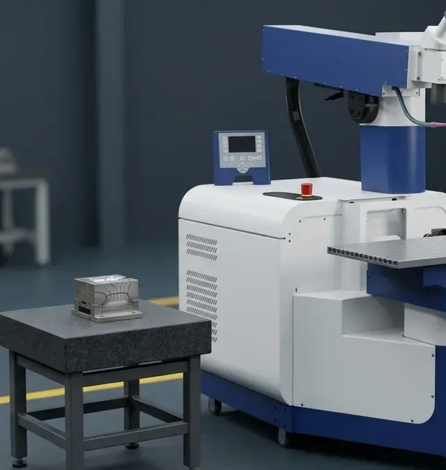
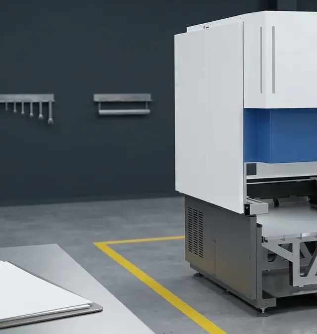
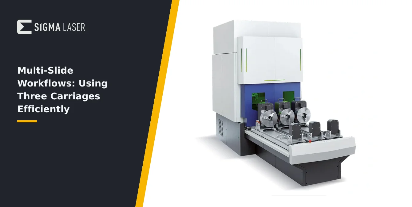
The Simass Slide system is engineered for high-throughput laser welding by integrating three fully independent slides (Einschubmodule) within a single automated cell. Each slide moves into the working area separately, allowing operators to load and unload parts outside the welding cabin while welding operations continue on another slide. This parallelization is central to minimizing non-productive time and maximizing cell utilization.
During production, while one slide is actively engaged in welding inside the protected process zone, the other two slides remain accessible from outside the cabin. Operators can safely remove finished components and load new workpieces without interrupting the ongoing welding cycle. This design eliminates the need to wait for a full cycle to finish before handling parts, reducing overall downtime between welds.
The independent movement of each slide is coordinated via the system’s control software, which ensures that only one slide enters the welding area at a time. This approach not only streamlines workflow but also enhances operator safety by maintaining a clear separation between the active laser zone and the manual loading/unloading area. The modularity of the slides further allows for flexible adaptation to varying part sizes and production requirements.
In practical terms, this means operators can prepare the next batch of parts or perform post-weld inspections on completed pieces while the laser is in operation. The result is a continuous workflow that keeps the laser welding cell productive, supporting demanding production schedules in tooling, mold repair, and other industrial applications.
| Parameter | Specification |
|---|---|
| Rotation Axis | Motorised, pivotable |
| Chuck Type | 315 mm three-jaw chuck |
| Workpiece Capacity | Up to 500 mm diameter, 1500 mm length |
| Processing Orientation | Horizontal and vertical (pivotable axis) |
| Welding Capability | Continuous circumferential, indexed, or segmented welds |
Each Slide Is a Rotary Station
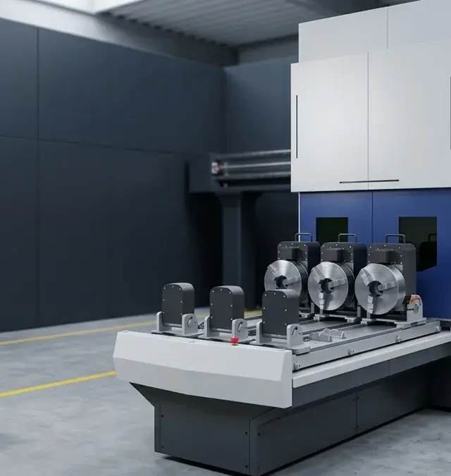
Every slide in the Simass Slide system functions as a dedicated rotary welding station. Each is equipped with a motorised, pivotable rotation axis and a 315 mm three-jaw chuck, providing secure, precise clamping for a wide variety of cylindrical or irregularly shaped workpieces. The rotation axis is not fixed in orientation; it can be pivoted to allow both horizontal and vertical processing, giving operators flexibility in how they approach each welding task.
This configuration supports workpieces up to 500 mm in diameter and 1500 mm in length, accommodating large molds, pipes, and tooling components typical in heavy industry and mold repair. The motorised rotation enables continuous circumferential welding, as well as indexed or segmented welds, depending on the part geometry and welding requirements.
For each slide, the ability to pivot the rotation axis means that welds can be performed on the side, top, or end faces of a part without the need for complex fixturing or repositioning. This not only saves setup time but also improves weld consistency, as the workpiece remains securely clamped throughout the process. The three-jaw chuck ensures concentricity and repeatable positioning, which is critical for multi-pass or multi-location welds.
Operators should routinely inspect the chucks for signs of wear, dust, or misalignment, as these factors can affect both the quality of the weld and the repeatability of the workflow. Regular maintenance of the rotary mechanisms ensures smooth operation and extends the service life of the equipment, supporting reliable, high-precision welding cycles.
| Workflow Pattern | Description |
|---|---|
| Weld-While-Loading | Laser welds on one slide while operators load/unload on others |
| Staggered Batch Processing | Offset start times for each slide to create a rolling sequence |
| Part Family Pairing | Group similar parts across slides for batch programming and reduced changeovers |
| Program Organization | Software supports organizing programs by slide and part type |
Workflow Patterns That Pay
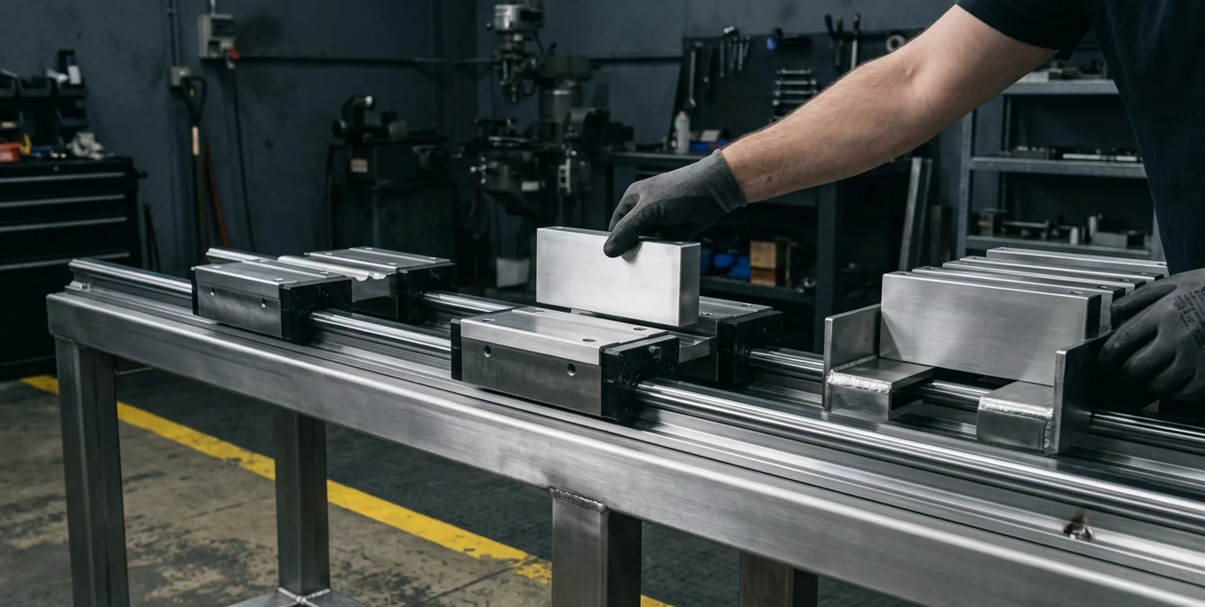
Efficient use of the multi slide three carriages workflow hinges on adopting proven operational patterns that exploit the system’s parallelism. One foundational pattern is the weld-while-loading approach: while the laser is welding on one slide, operators simultaneously unload finished parts and load new workpieces onto the other slides outside the cabin. This overlap minimizes idle time, keeping the laser in near-continuous operation.
Staggered batch processing is another effective strategy. By offsetting the start times of each slide, operators can create a rolling sequence where each slide is at a different stage of the cycle—one welding, one being loaded, and one being unloaded. This sequencing supports takt-time production, where the workflow is balanced to meet a fixed output rate per unit time. Such synchronization is particularly valuable in series production or when handling part families with similar geometries and weld requirements.
Pairing related parts or part families across the slides can also streamline changeovers and reduce the frequency of parameter adjustments. For example, grouping similar molds or tooling inserts allows for batch programming and reduces the risk of operator error when switching between dissimilar jobs. The system’s software supports organizing programs by slide and part type, further simplifying workflow management.
Ultimately, the most productive workflows are those that maintain a steady rhythm between welding and handling, minimize waiting periods, and leverage the independent movement of each slide to its fullest. Operators should regularly review takt times and adjust loading/unloading routines to keep pace with the welding cycle, ensuring that the laser cell operates at maximum efficiency.
Keeping Slides Out of Each Other’s Way
Safe and efficient operation of a multi-slide system requires disciplined management of slide movements to prevent collisions and ensure smooth workflow transitions. The working area is zoned so that only one slide enters the welding cabin at a time, with the others remaining in their designated loading/unloading positions outside the process zone. This zoning is enforced both physically and via the control software, which sequences slide movements according to programmed routines.
Operators must be vigilant when preparing slides for entry, confirming that the intended slide has a clear path and that no obstructions or loose items are present. It is good practice to visually inspect the travel path and use the system’s status indicators to verify slide positions before initiating movement. Program organization is critical: each slide should have its own set of programs or routines, clearly labeled and stored in the control system to avoid accidental cross-activation.
Collision discipline extends to manual interventions as well. Operators should never attempt to override interlocks or force slide movements outside of programmed sequences. In multi-operator environments, clear communication protocols and handover procedures help prevent conflicting commands or unexpected slide entries. The use of physical barriers or warning lights can further reinforce safe zones and prevent accidental encroachment into the active welding area.
Routine checks of limit switches, sensors, and interlocks are essential for maintaining the integrity of the zoning system. Any irregularities in slide movement or unexpected alarms should be investigated and resolved before resuming production. Consistent adherence to these practices ensures both operator safety and uninterrupted workflow.
Verifying the Combined Workflow
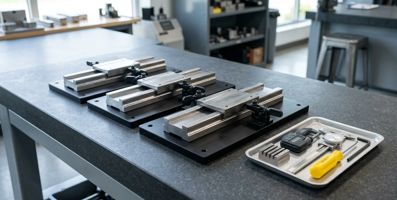
Before commencing full production, it is essential to verify the combined workflow of all three slides to ensure reliable, repeatable operation. Start by testing each slide independently: perform a series of dry runs (without laser activation) to confirm that the slide moves smoothly into and out of the welding area, clamps the part securely, and returns to its loading position without interference or hesitation.
Check the repeatability of each slide’s positioning by cycling it multiple times and measuring the alignment of the workpiece in the chuck. Any deviations in position or clamping should be addressed through mechanical adjustment or maintenance. Once individual slide performance is confirmed, proceed to a full dry-run cycle involving all three slides in sequence. Observe the timing and transitions between slides, ensuring that each slide enters and exits the cabin without conflict and that the control system correctly manages the sequence.
During these tests, monitor the response of safety interlocks, status indicators, and any alarms generated by the system. Confirm that the software correctly enforces the one-slide-at-a-time rule and that manual overrides are disabled during automated cycles. Record cycle times for each step and compare them to your planned takt time to identify any bottlenecks or delays.
Once the dry-run cycle is validated, perform a test weld cycle with actual parts, closely observing the transitions and handling procedures. Solicit feedback from all operators involved to identify potential improvements in slide preparation, loading routines, or program organization. Document the verified workflow and establish it as the standard operating procedure for multi-slide production.
Frequently Asked Questions
How does the three-carriage system reduce downtime?
The three-carriage system allows operators to load and unload parts on two slides outside the welding cabin while the third slide is welding. This parallel handling eliminates waiting periods between welds, significantly reducing downtime and increasing throughput.
What part sizes can each slide handle?
Each slide is equipped with a 315 mm three-jaw chuck and can process parts up to 500 mm in diameter and 1500 mm in length. This accommodates large molds, pipes, and tooling components typical in heavy industrial applications.
How do I prevent collisions between slides?
Collision prevention relies on strict zoning: only one slide enters the welding area at a time, enforced by control software. Operators should verify slide positions, follow programmed routines, and never override safety interlocks or attempt manual movements outside the approved sequence.
What is the best way to verify workflow reliability?
Begin by dry-running each slide independently to check movement and repeatability. Then execute a full cycle with all slides in sequence, monitoring for smooth transitions and correct timing. Address any issues before starting live welds to ensure safe, efficient operation.