
- The Rotary Toolkit
- Concentricity Before Power
- Synchronizing Rotation and Pulses
- Start, Overlap, Fade-Out
- Shielding Gas Around the Circumference
- Inspection and Upkeep
- Frequently Asked Questions
- How do I ensure perfect concentricity before rotary welding?
- What is the best way to synchronize rotation speed and laser pulses?
- How can I achieve full shielding gas coverage during orbital welding?
- What maintenance steps are critical for rotary welding devices?
- Related Articles
Quick Answer: To achieve perfect rotary orbital welds, use precision rotary tooling, ensure concentricity before welding, synchronize rotation with pulse timing, overlap the seam start/end, maintain full shielding gas coverage, and regularly inspect both welds and rotary devices. Adhering to these best practices ensures consistent, high-quality orbital welds on pipes, rings, and shafts.
| Feature | Simass Rotate | Motor-Driven Rotary Device |
|---|---|---|
| Type | Automation module (integrated rotary table) | Accessory (add-on rotary device) |
| Control | Programmable: fixed-clock (indexed) or freely programmable rotation | Continuous, programmable rotation |
| Suitable for | High-volume, automated rotary welding | Manual or semi-automated workflows |
| Integration | Welding cell (automation system) | Open-frame machines |
| Part Handling | Wide range of diameters and part weights | Secures rings, pipes, shafts without custom fixtures |
| Software | Sigomatic / Sigomatic Pro | Sigomatic / Sigomatic Pro |
| Welding Modes Supported | Pulsed and continuous wave (CW) fibre laser (machine-dependent) | Integrated with laser welding sequence |
| Load Capacity | Unlimited (machine-dependent) | Unlimited (machine-dependent) |
Both solutions are designed for precise, repeatable rotation and integration with Sigma Laser open-frame machines.
The Rotary Toolkit
Rotary orbital welding on pipes, rings, and shafts demands specialized equipment to achieve consistent, high-quality seams. Sigma Laser provides two primary solutions: the Simass Rotate automation module and the Motor-Driven Rotary Device accessory. Each is engineered for precise, repeatable rotation of round workpieces, from delicate micro-tubes to heavy industrial pipes.
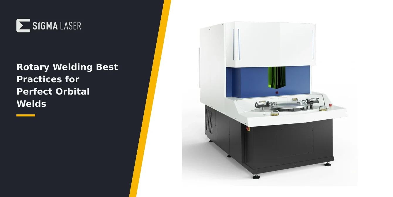
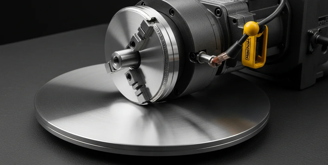
The Simass Rotate module integrates a precision rotary table into the welding cell. Operators can select between fixed-clock (indexed) or freely programmable rotation, allowing both high-speed serial production and custom one-off jobs. The system ensures high accuracy at elevated rotation speeds, supporting both pulsed and continuous wave (CW) fibre laser welding modes, depending on the machine configuration. The rotary table’s robust design accommodates a wide range of diameters and part weights, making it suitable for demanding sectors such as tooling, medical, and automotive manufacturing.
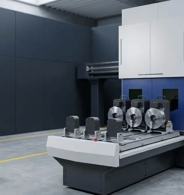
For manual or semi-automated setups, the Motor-Driven Rotary Device is a versatile accessory. It secures round parts—such as rings, pipes, and shafts—without the need for custom fixtures. The device provides continuous, programmable rotation, ensuring smooth circumferential welds. Operators can control the rotation via Sigomatic or Sigomatic Pro software, integrating rotary motion with the laser welding sequence for optimal process control.
- Simass Rotate: for high-volume, automated rotary welding with programmable control.
- Motor-Driven Rotary Device: for flexible, secure rotation in manual or semi-automated workflows.
Both options are designed for integration with Sigma’s open-frame machines, supporting unlimited load capacity and a broad spectrum of part sizes.
Concentricity Before Power
Achieving perfect rotary orbital welds begins with precise concentricity. Before initiating any welding sequence, operators must ensure that the workpiece is centered accurately within the rotary device or table. Even minor deviations in concentricity—known as runout—can lead to uneven energy input, inconsistent bead profiles, and potential weld defects.
To dial in runout, mount the part securely in the rotary chuck or fixture. Slowly rotate the part by hand or at low speed while observing the seam path through the Leica stereo microscope or other alignment aids. Look for any lateral movement or wobble that would indicate off-center mounting. Use dial indicators or reference marks to measure total indicated runout (TIR) and adjust the chuck or jaws as needed until the seam path remains stable throughout a full rotation.
Poor centering can cause the laser spot to drift relative to the weld joint, resulting in variable penetration depth, incomplete fusion, or excessive heat input at certain points. For critical applications—such as medical device or mold repair—tight runout tolerances are essential to ensure weld integrity and dimensional accuracy.
Always confirm concentricity before powering the laser. This step is foundational: correcting runout after welding has started is not feasible and will compromise weld quality. Document your alignment process in production records for traceability and repeatability.
Synchronizing Rotation and Pulses
Synchronization of rotary motion and laser pulse timing is critical for producing uniform, defect-free orbital welds. In pulsed laser welding, the rotation speed of the workpiece must be matched to the pulse frequency and duration to achieve the desired pulse overlap and seam continuity. For continuous wave (CW) welding, a steady, even rotation ensures consistent energy distribution around the circumference.
Begin by determining the optimal pulse frequency and duration for your material and joint geometry—refer to your material parameter table or established process guidelines. Calculate the required rotation speed so that each laser pulse overlaps the previous one sufficiently to avoid gaps or weak points in the seam. Insufficient overlap may result in porous or undercut welds, while excessive overlap can cause overheating and distortion.
With programmable rotary devices, use the Sigomatic or Sigomatic Pro software to set and verify rotation parameters. Monitor the live feedback on axis positions and process status to confirm that rotation and pulsing are synchronized throughout the weld cycle. For CW welding, focus on maintaining a constant rotation speed that matches the desired linear weld rate.
- Pulse overlap: critical for seamless, leak-tight joints.
- Continuous rotation: ensures even energy input and minimizes heat-affected zone (HAZ) variation.
Test welds on sample parts are recommended to fine-tune synchronization before production runs. Record successful parameter sets for future reference.
Start, Overlap, Fade-Out
Proper management of the weld start and stop points is essential for a flawless circumferential seam. Industry best practice dictates that the end of the weld should overlap the start by a controlled amount, ensuring a fully closed joint with no gaps or weak spots. This overlap compensates for any minor inconsistencies at the seam start and guarantees structural integrity.
To execute this, mark the seam start location clearly and program the rotary device to complete slightly more than one full revolution. As the weld approaches the starting point, monitor the overlap zone closely—using the microscope or live camera feed—to avoid excessive buildup or underlap. The goal is a smooth, even transition with no visible step or crater.
At the end of the weld, apply a fade-out technique to reduce the risk of end craters or localized overheating. This typically involves gradually reducing the laser power or pulse energy over the final few millimeters of the seam. Controlled fade-out minimizes residual stresses and prevents the formation of shrinkage cracks or surface depressions.
Document the overlap and fade-out parameters in your process instructions. Consistent execution of these steps is vital for applications where seam quality and appearance are critical, such as medical tubing, high-pressure vessels, or visible mold repairs.
Shielding Gas Around the Circumference
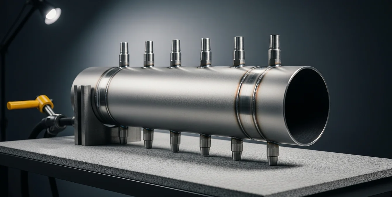
Effective shielding gas coverage is fundamental to achieving clean, oxidation-free rotary orbital welds. Unlike linear welds, orbital seams require continuous protection around the entire circumference of the joint. Inadequate shielding can lead to discoloration, porosity, or oxidation, especially on reactive metals such as titanium or stainless steel.
Develop a full-coverage shielding strategy tailored to your part geometry and welding position. Position gas nozzles or diffusers to envelop the entire weld zone, ensuring that shielding gas—typically argon—flows uniformly as the part rotates. For larger or complex shapes, consider auxiliary shielding setups or trailing shields to maintain coverage at all points on the seam.
Monitor gas flow rates and nozzle positioning before and during welding. Use test welds to verify that the entire circumference remains free of oxidation or contamination. Adjust gas flow as needed to compensate for part size, rotation speed, and environmental factors such as drafts or ventilation.
- Uniform gas coverage: prevents oxidation and discoloration.
- Adjustable nozzle positions: accommodate different part sizes and geometries.
Document your shielding setup for each part type, and periodically review gas supply and delivery system integrity to ensure continued weld quality.
| Step | Best Practice |
|---|---|
| 1. Tooling | Use precision rotary tooling (Simass Rotate or Motor-Driven Rotary Device) |
| 2. Concentricity | Ensure workpiece is centered and runout is minimized before welding |
| 3. Synchronization | Match rotation speed with pulse timing or maintain steady speed for CW welding |
| 4. Seam Overlap | Overlap weld start/end for a fully closed joint |
| 5. Shielding Gas | Maintain full coverage around the circumference |
| 6. Inspection | Regularly inspect welds and rotary devices |
Following these steps ensures consistent, high-quality orbital welds.
Inspection and Upkeep
Consistent weld quality depends on rigorous inspection and regular maintenance of both the welded parts and the rotary equipment. After each welding cycle, perform a thorough visual and dimensional inspection of the seam. Look for uniform bead appearance, complete fusion, absence of undercut or overlap, and proper seam closure at the overlap zone. Use measurement tools or gauges to verify critical dimensions and tolerances, especially for applications with tight fit-up requirements.
Equally important is the upkeep of the rotary device or table. Inspect the chuck or clamping mechanism for signs of wear, dust buildup, or misalignment. Clean the jaws and rotating surfaces regularly to prevent slippage or runout issues. Check for smooth, vibration-free operation by power-cycling the rotary device before each production run. Any irregular noises, hesitations, or startup issues should be addressed immediately to avoid compromising weld quality.
Document all inspection and maintenance activities in a logbook or digital record. Scheduled preventive maintenance—such as lubrication, alignment checks, and component replacement—extends the service life of the rotary equipment and minimizes unplanned downtime.
- Visual and dimensional seam inspection after every weld.
- Routine cleaning and alignment checks of rotary devices.
- Power-cycle tests to confirm smooth startup and operation.
Adhering to these inspection and upkeep protocols ensures reliable, repeatable orbital welds and maximizes equipment performance over time.
Frequently Asked Questions
How do I ensure perfect concentricity before rotary welding?
Secure the part in the rotary chuck, rotate it slowly, and observe the seam path for any lateral movement. Use dial indicators or reference marks to measure runout. Adjust the chuck or jaws until rotation is smooth and the seam path remains stable throughout a full revolution.
What is the best way to synchronize rotation speed and laser pulses?
Calculate the required rotation speed so each laser pulse overlaps the previous one adequately. Set rotation and pulse parameters via Sigomatic or Sigomatic Pro, and verify synchronization with test welds before starting production. Adjust as needed for your specific material and seam geometry.
How can I achieve full shielding gas coverage during orbital welding?
Position gas nozzles or diffusers to cover the entire weld zone as the part rotates. Adjust flow rates and nozzle positions for different part sizes. Test welds help confirm uniform coverage and absence of oxidation or discoloration around the full circumference.
What maintenance steps are critical for rotary welding devices?
Regularly inspect chucks for wear, dust, or misalignment. Clean all clamping and rotating surfaces, and power-cycle the device to ensure smooth operation. Document maintenance activities and address any irregularities before starting production to maintain weld quality.