
- What Arrives: the Sirius Light at a Glance
- Choosing and Preparing the Location
- Positioning and Locking the Machine
- First Power-Up and Safety Checks
- Jogging the Five Axes and the Optics
- Your First Test Weld
- Frequently Asked Questions
- What power supply is required for the Sirius Light?
- How do I ensure the Sirius Light is stable before welding?
- Is an external chiller needed for cooling?
- What should I use for my first test weld?
- Related Articles
Quick Answer: To set up the Sirius Light for the first time, prepare a level, non-reflective workspace with 380V/3Ph/50Hz power, position and lock the mobile unit securely, perform all safety checks, then jog all axes before running your first test weld on scrap material. Follow all supplied safety guidelines throughout.
| Parameter | Value |
|---|---|
| Laser Type | Nd:YAG (flash-lamp pumped) |
| Wavelength | 1064 nm |
| Power Options | 60 – 500 W (modular) |
| Pulse Duration | 0.5 – 20 ms (adjustable) |
| Repetition Rate | up to 40 Hz |
| Spot Diameter | 0.2 – 2.0 mm (adjustable) |
| Axes | 5-axis (X, Y, Z, C, D) |
| Axis Resolution | 0.01 mm |
| Reach (Articulating Arm) | up to 1830 mm |
| Load Capacity | Unlimited (open-frame) |
| Max Part Height | up to 450 mm |
| Optics | Leica 10× stereo microscope, 100 mm working distance |
| Cooling | Integrated closed-loop water cooling (no external chiller) |
| Mobility | Heavy-duty mobile unit with castor locks |
All values are as described in the article body. For full technical details, refer to the official Sigma Laser documentation.
What Arrives: the Sirius Light at a Glance
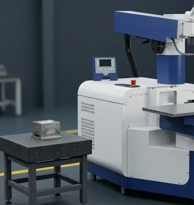
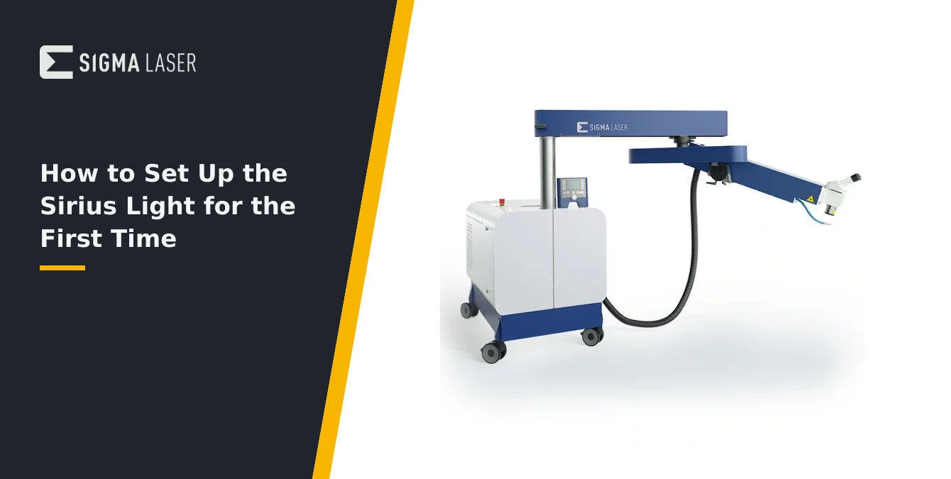
The Sirius Light is a heavy-duty mobile laser welding system designed for demanding applications such as mold and tool repair, large-part fabrication, and flexible on-site operations. It operates with a pulsed Nd:YAG laser at 1064 nm, providing precise energy delivery suitable for a wide range of metals and alloys. The modular design supports power options from 60 to 500 W, with pulse durations adjustable between 0.5 and 20 ms and repetition rates up to 40 Hz. The spot diameter is adjustable from 0.2 to 2.0 mm, allowing fine control over weld geometry.
One of the Sirius Light’s defining features is its exceptional mobility and reach. The articulating arm extends up to 1830 mm, enabling access to large or fixed workpieces directly on the shop floor, including molds and dies weighing even 25 tonnes or more. The open-frame architecture imposes no load capacity limit, making it suitable for the heaviest industrial components.
Precision is ensured through axis drives with 0.01 mm resolution, supporting fine positioning for intricate repair and joining tasks. The system includes a Leica 10× stereo microscope for detailed visual alignment and inspection. The integrated closed-loop water cooling system maintains stable operation without the need for an external chiller, simplifying installation and maintenance.
Upon delivery, the Sirius Light arrives as a ready-to-operate unit, with all core components pre-installed. Accessories such as the optics head, microscope, and control panel are securely packaged for transport. The system is accompanied by comprehensive safety documentation and operator manuals, which should be reviewed before any setup steps are undertaken.
| Requirement | Specification |
|---|---|
| Floor | Level, stable, non-reflective, supports machine and heavy workpieces |
| Clearance | At least 2 meters in all directions from base unit (to accommodate 1830 mm reach) |
| Electrical Supply | 380V, 3-phase, 50Hz (dedicated circuit recommended) |
| Accessibility | Power disconnect and emergency stop must remain accessible |
| Environment | Free of vibration, excessive dust, drafts; avoid reflective surfaces |
| Laser Area | Clearly marked, with warning signage and floor markings |
| Operator Space | Adequate for movement, material handling, and maintenance |
These requirements are directly stated in the article for safe and effective Sirius Light operation.
Choosing and Preparing the Location
Proper site preparation is critical for safe and effective operation of the Sirius Light. Begin by selecting a location with a level, stable floor capable of supporting the machine’s weight and the movement of heavy workpieces. The area must allow for the full extension and articulation of the laser arm—ensure at least 2 meters of unobstructed clearance in all directions from the base unit to accommodate the maximum 1830 mm reach.
Electrical requirements are 380V, 3-phase, 50Hz supply, with a dedicated circuit recommended to prevent voltage fluctuations during operation. Verify that the power source is within reach of the machine’s connection point, and that all wiring complies with local industrial electrical codes. Position the machine so that the power disconnect and emergency stop remain easily accessible at all times.
The workspace should be non-reflective and free of unnecessary metallic surfaces to minimize stray laser reflections. This is essential for operator safety and to maintain the integrity of the laser process. Mark the laser-controlled area clearly, as specified in the supplied safety documentation, and install appropriate warning signage and floor markings.
Ensure adequate space for operator movement, material handling, and maintenance access. If the Sirius Light will be used on large or awkwardly shaped workpieces, plan for safe paths to roll the machine into position. Avoid placing the system near sources of vibration, excessive dust, or direct drafts, as these can affect both safety and weld quality.
Positioning and Locking the Machine
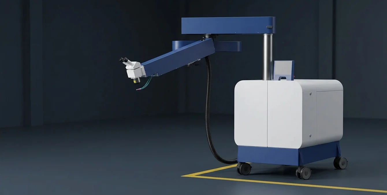
The Sirius Light’s mobility is a key advantage, but secure positioning is essential before any operation. Roll the machine to the prepared workspace, approaching the workpiece so that the laser arm can reach the intended weld area without overextending or creating awkward angles. Use the built-in handles and guidance points to maneuver the unit safely and precisely.
Once in position, engage the castor locks on all wheels to prevent any movement during operation. Double-check that the unit is stable and level; instability can compromise both safety and weld accuracy. Before extending the laser arm, verify that there is no risk of collision with surrounding equipment, fixtures, or the workpiece itself. The arm should move freely through its full range without obstruction.
Stability verification is crucial, especially when working at maximum reach or with heavy tooling attached. Gently test the base for any rocking or shifting, and adjust the position if necessary. Confirm that the power cable and any accessory connections are routed safely, away from walkways or moving parts.
With the machine locked and stable, perform a final visual inspection of the workspace. Remove any loose objects, tools, or reflective materials from the immediate area. Ensure that all safety barriers, curtains, or shields are in place as outlined in the safety documentation. Only proceed with setup once you are confident that the Sirius Light is secure and the environment is compliant with all safety requirements.
| Step | Action |
|---|---|
| Safety Documentation | Review all supplied guidelines and manuals |
| Personnel | Ensure all operators are trained and equipped with 1064 nm-rated eyewear |
| Laser Area | Mark and secure with warning signs and barriers |
| Emergency Controls | Locate and ensure access to emergency stop and power disconnect |
| Interlocks | Verify all safety interlocks are engaged and functional |
| Power-Up | Follow manual sequence; cooling system activates automatically |
| Diagnostics | Check system status, axis readiness, and interlocks via Sigomatic panel |
| Axis Jogging | Test all five axes for smooth, precise movement (0.01 mm resolution) |
| Optics Check | Adjust and verify Leica microscope and optics head movement |
Checklist summarizes the step-by-step safety and operational procedures as described in the article.
First Power-Up and Safety Checks
Before powering up the Sirius Light for the first time, review the supplied safety guidelines thoroughly. Confirm that all operators and personnel in the vicinity are trained and authorized, and that everyone is equipped with appropriate laser safety eyewear rated for 1064 nm. The laser-controlled area should be clearly marked, with warning signs and barriers in place as specified in the documentation.
Locate and familiarize yourself with the emergency stop button and main power disconnect. These must be accessible at all times during operation, setup, and maintenance. Verify that all interlock systems are engaged and functioning—these are critical for preventing unintentional laser emission or movement during setup.
Power up the Sirius Light using the main switch, following the sequence outlined in the operator manual. The integrated closed-loop water cooling system will activate automatically; monitor the system status indicators to confirm that coolant flow and temperature are within operational limits. No external chiller is required, simplifying the installation process and reducing setup time.
Use the Sigomatic control panel to check system diagnostics, including laser source status, axis readiness, and interlock engagement. Address any alerts or warnings before proceeding. Only continue with axis testing and alignment once all safety checks have been completed and the system reports normal operating status. Adherence to these procedures is essential for operator safety and to protect the equipment from damage.
Jogging the Five Axes and the Optics
With the Sirius Light powered and all safety checks complete, proceed to test the full range of motion for each of the five axes: X, Y, Z, C (rotation), and D (tilt or secondary rotation). Use the Sigomatic control panel or the manual jog controls to move each axis incrementally, observing for smooth, unobstructed travel. The axis drives provide 0.01 mm resolution, allowing for highly precise positioning—verify that each axis responds accurately to control inputs.
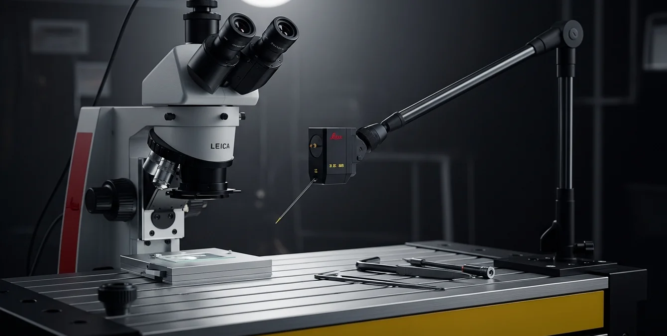
Extend the laser arm through its full reach (up to 1830 mm) and ensure there is no interference from surrounding equipment or fixtures. Pay particular attention to cable routing and slack, ensuring that no cables are pinched or strained during movement. The Leica 10× stereo microscope is mounted on the optics head, providing a 100 mm working distance for fine alignment and inspection. Adjust the microscope position as needed for comfortable viewing and clear focus on the intended weld area.
Test the optics head movement and all adjustment mechanisms, including focus, spot size, and any available beam deflection options. Confirm that the optics remain stable throughout the range of motion and that the field of view through the microscope is unobstructed. If using optional accessories such as swivel optics or wire feed, verify their integration and function at this stage.
- Move each axis to its travel limits and back to home position
- Check for abnormal noises, resistance, or misalignment
- Confirm that all axis positions are correctly reported in the control software
Any irregularities should be addressed before proceeding to actual welding operations. This axis and optics check ensures both operator safety and the accuracy of subsequent welds.
Your First Test Weld
Before beginning production work, perform a test weld using scrap material of the same alloy and geometry as your intended workpiece. This allows you to verify machine setup, parameter selection, and weld quality without risking valuable components. Position and secure the scrap piece within the Sirius Light’s working envelope, ensuring stable support and proper alignment under the optics head.
Set conservative pulse energy and duration parameters via the Sigomatic control panel, referencing your material parameter table or previous experience with similar alloys. Begin with lower energy settings to minimize the risk of overheating or excessive penetration. Initiate the weld sequence, observing the process through the Leica microscope for precise control and immediate feedback.
After completing the test weld, inspect the joint visually and, if possible, with auxiliary tools such as magnifiers or cross-section analysis. Look for signs of incomplete fusion, excessive heat-affected zone, or surface defects. Adjust pulse parameters incrementally as needed, repeating the test until optimal results are achieved. Document the successful settings and store them as a program in the machine’s memory for future reference.
This iterative test weld process is essential for validating both the Sirius Light’s setup and your chosen process parameters. It establishes a reliable baseline for production welding and helps ensure consistent, high-quality results from the outset.
Frequently Asked Questions
What power supply is required for the Sirius Light?
The Sirius Light requires a 380V, 3-phase, 50Hz industrial power supply. Ensure a dedicated circuit is available and that all connections comply with local electrical codes for safe, stable operation.
How do I ensure the Sirius Light is stable before welding?
After rolling the machine into position, lock all castors and check for any rocking or movement. Confirm the base is level and that the arm can extend fully without obstruction. Stability is essential for both safety and weld accuracy.
Is an external chiller needed for cooling?
No, the Sirius Light is equipped with an integrated closed-loop water cooling system. This maintains optimal operating temperature automatically, eliminating the need for an external chiller.
What should I use for my first test weld?
Use scrap material of the same alloy and geometry as your production workpiece. Start with conservative pulse settings, inspect the weld, and adjust parameters as needed to achieve optimal results before moving to actual parts.